2026
FSAE Pedal Box and Brake Rotors
- Problem
- Create the entire braking system of a formula style car, from the drivers feet to the wheels.
- Approach
- Detailed calculations led to getting correct rotor size, pedal ratio, and superb braking distances
- Result
- Stopping 180 kg of mass from 60-0 in 22.9 meters, less than half of an average road car.
FSAE Pedal Box and Brake Rotors
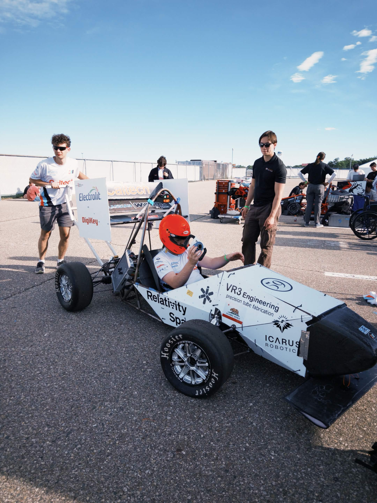
Joining the Caltech Formula SAE team gave me my first real engineering leadership role. The team had no functional brake system on the car, so I took over as Brakes System Lead Engineer. I had already worked on brakes for my personal car, which made the transition easier.
The project started with the fundamentals: mass distribution, center of gravity, load paths, and how weight transferred under braking, both statically and dynamically. From those calculations, I set target braking distances and stopping times. Those targets determined rotor size, pad size, and pad material. Working backward from the braking system, we calculated the pedal ratio, the relationship between the force applied by the driver's foot and the resulting hydraulic pressure.

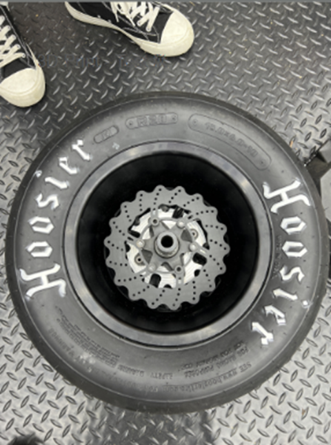
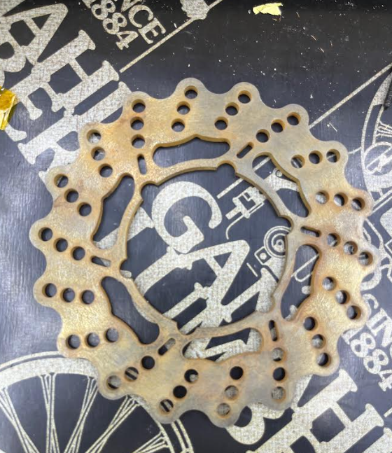
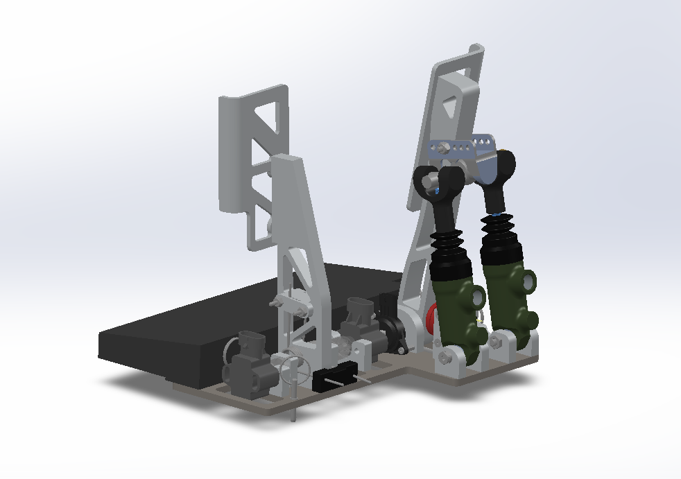
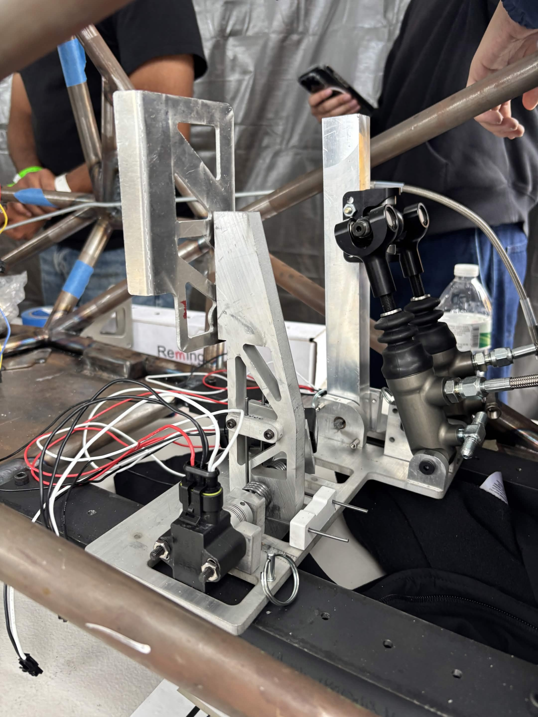
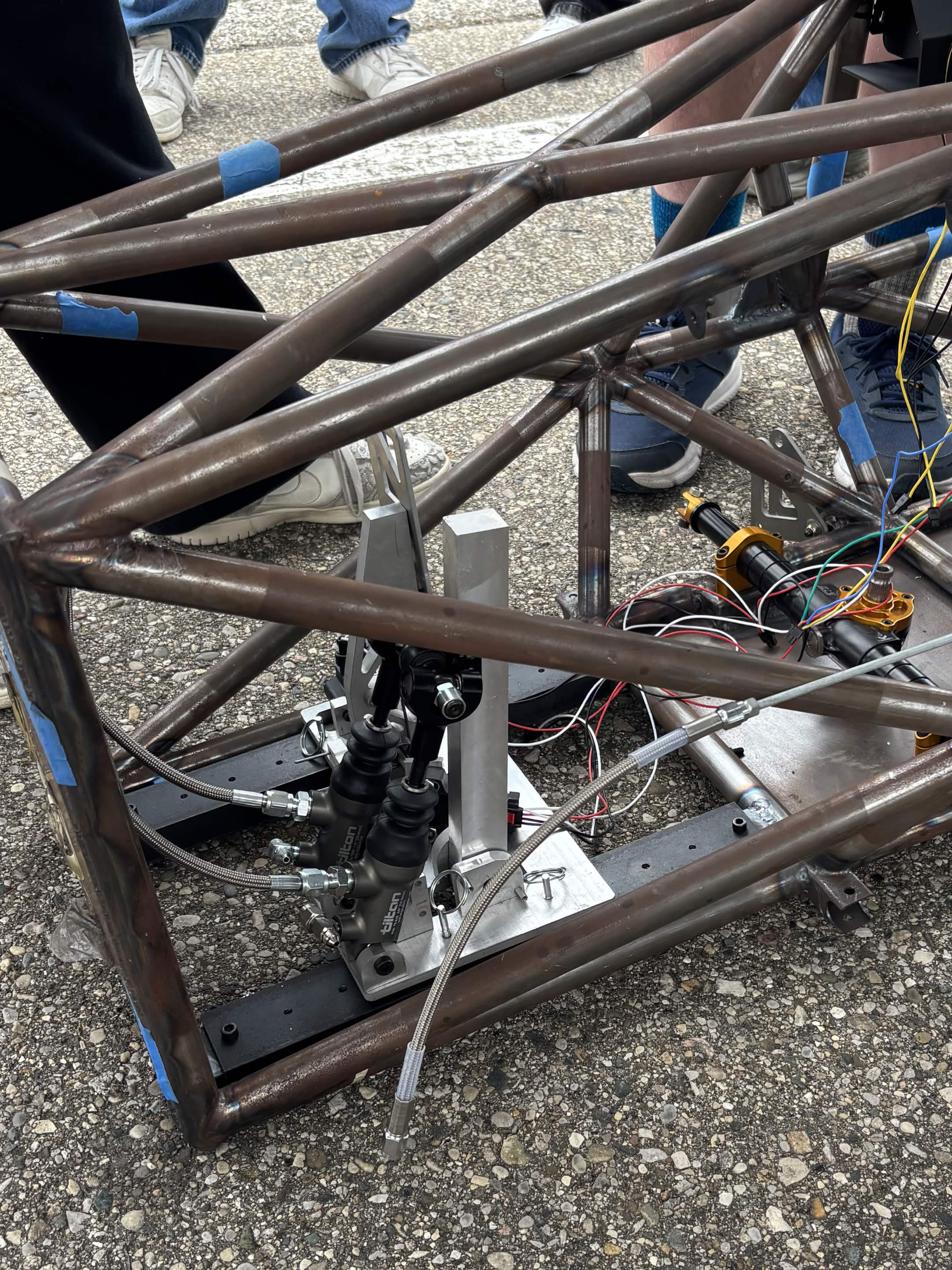
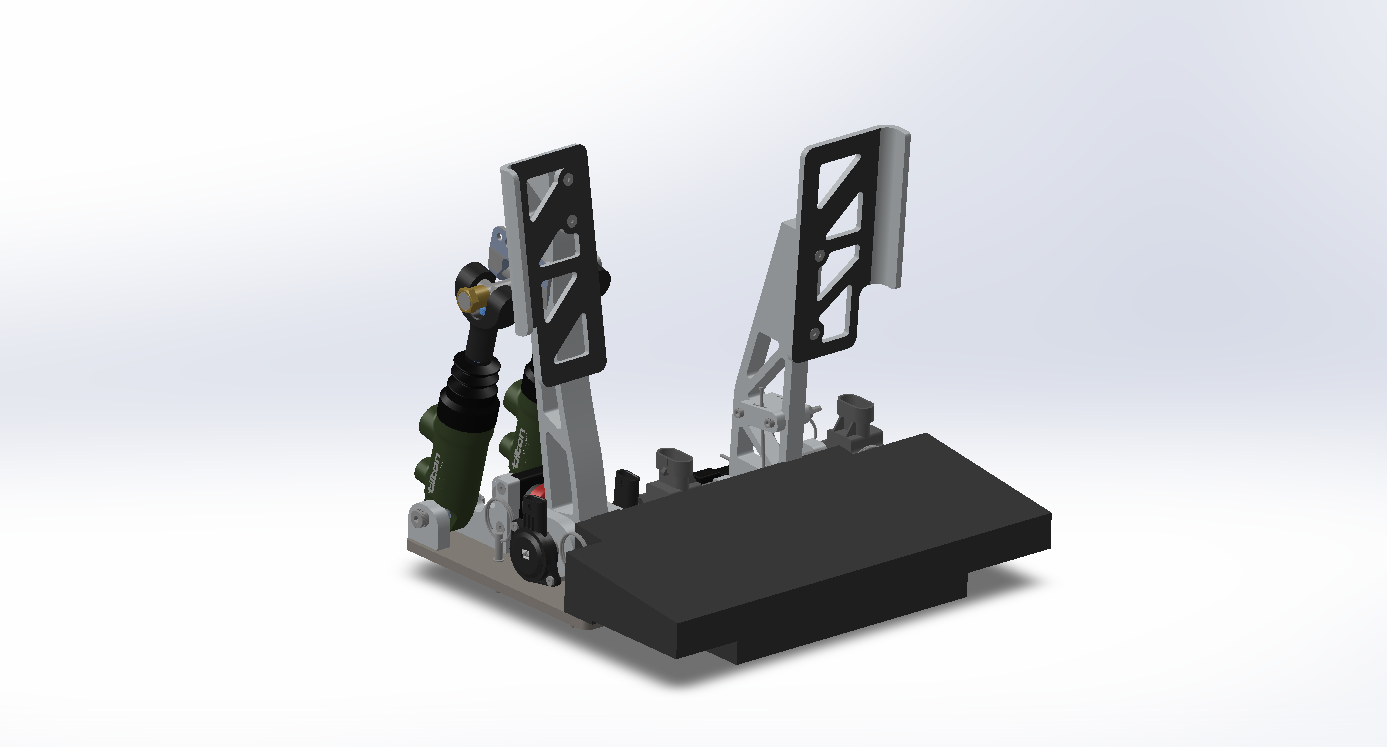
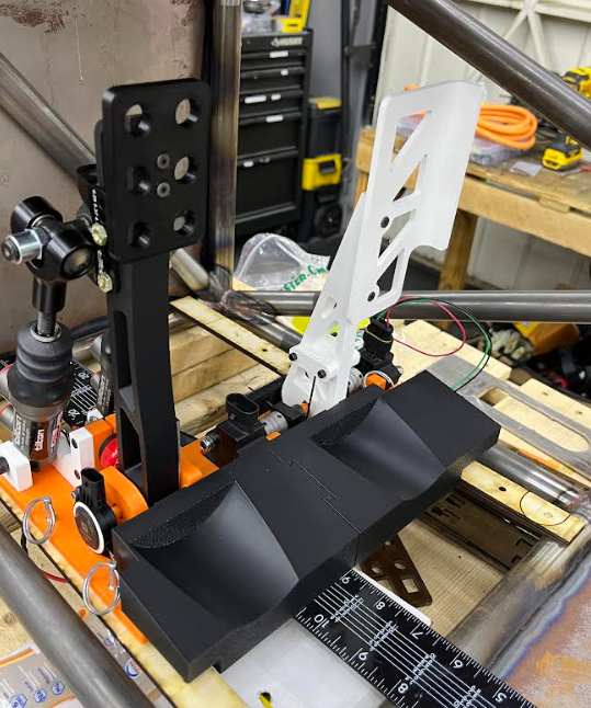
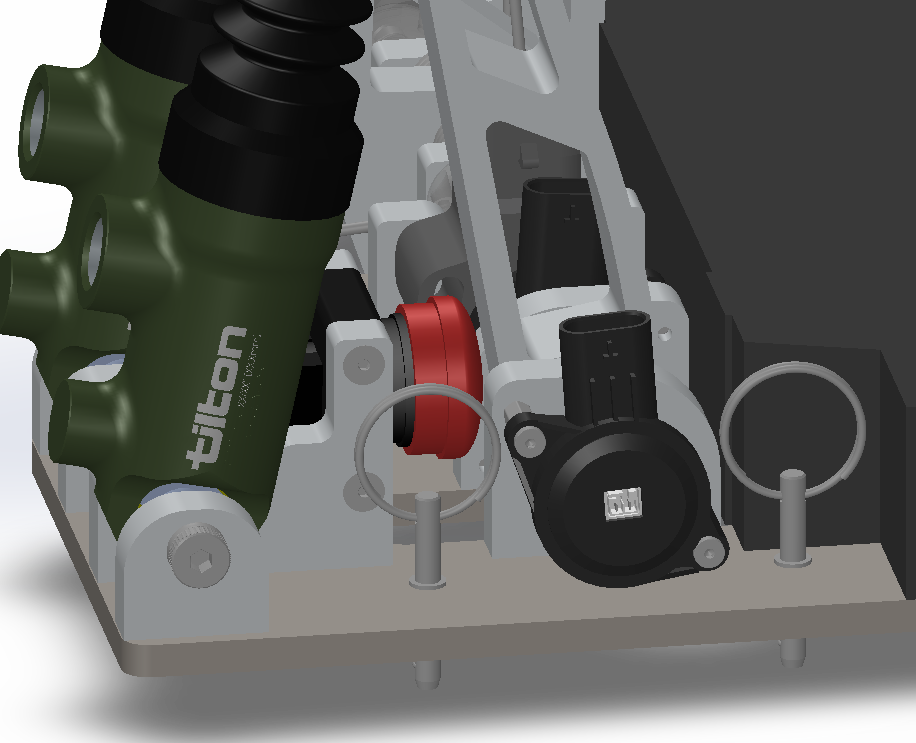
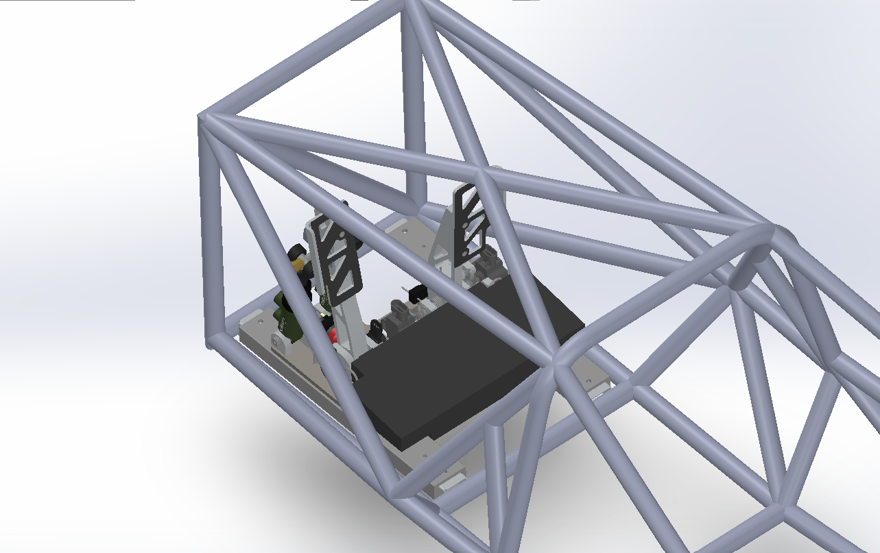
With the pedal ratio and rotors established, I moved into designing the pedalbox itself. The existing unit was two years old, overweight, and mechanically clunky, so I rebuilt it from scratch as a fully aluminum assembly, aside from the screws, master cylinders, and sensors. The first prototype exposed two major challenges: packaging the brake over travel switch (BOTS) in the available space, and tuning the accelerator pedal's spring feedback. I resolved the spring issue by sourcing larger springs, which gave the pedal a firm but not excessive resistance while still leaving room to fit the BOTS switch.
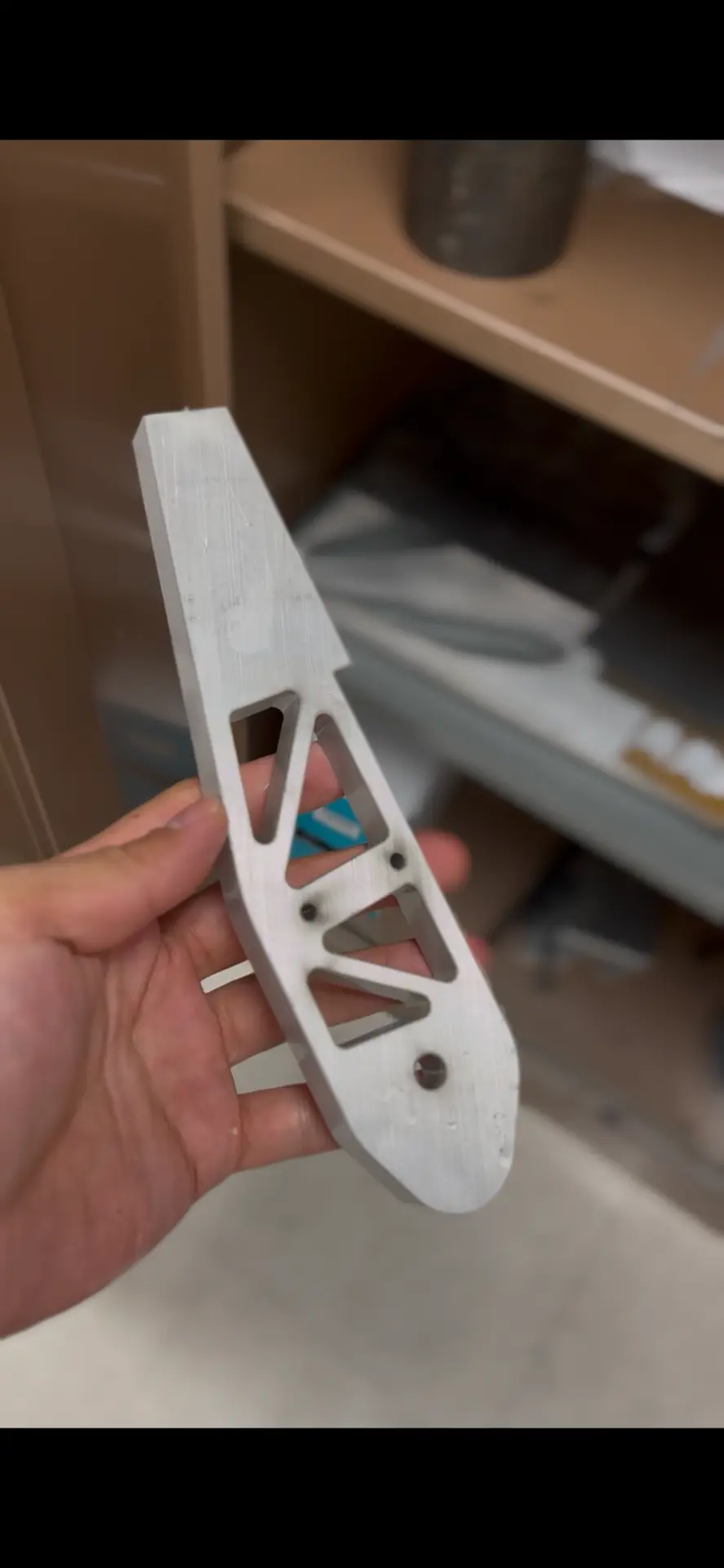
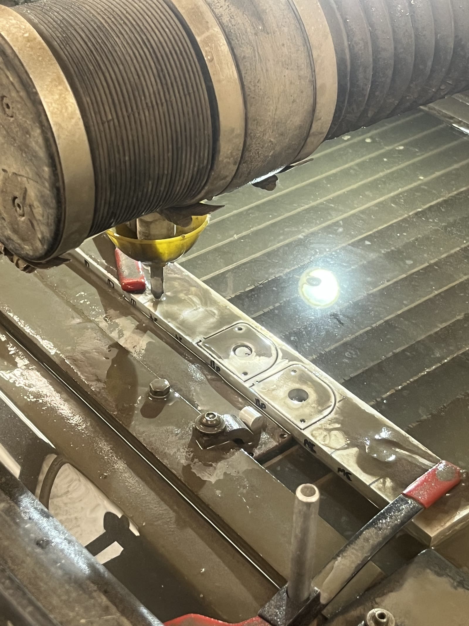
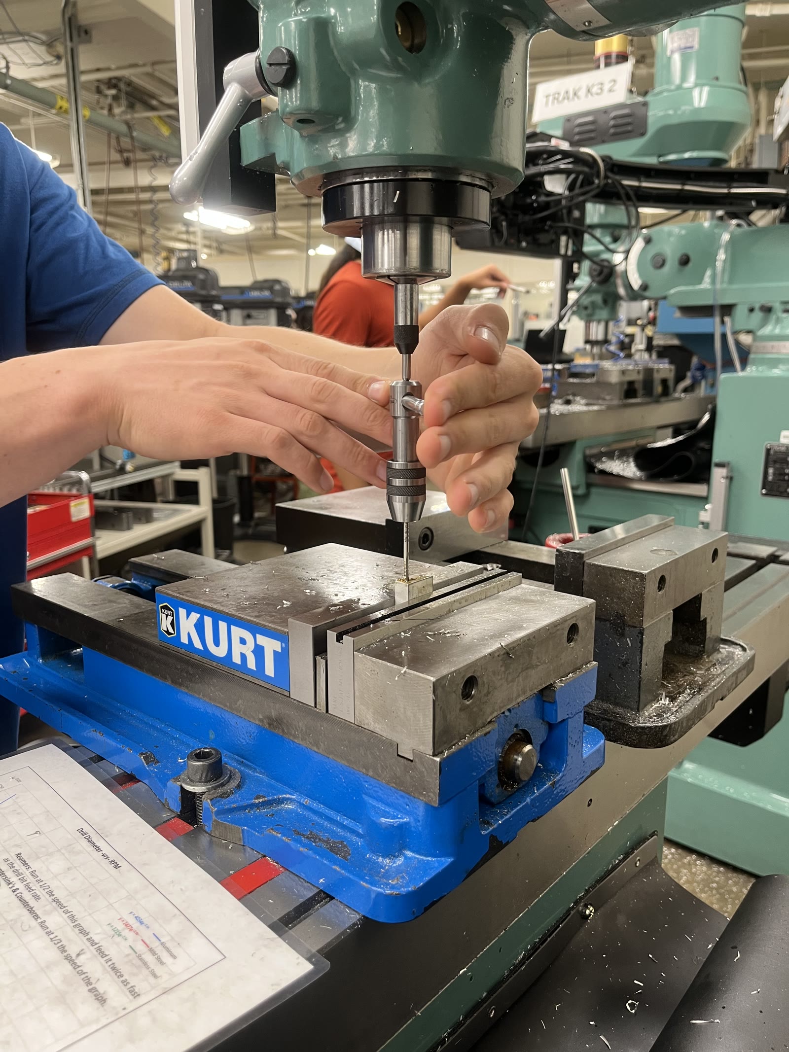
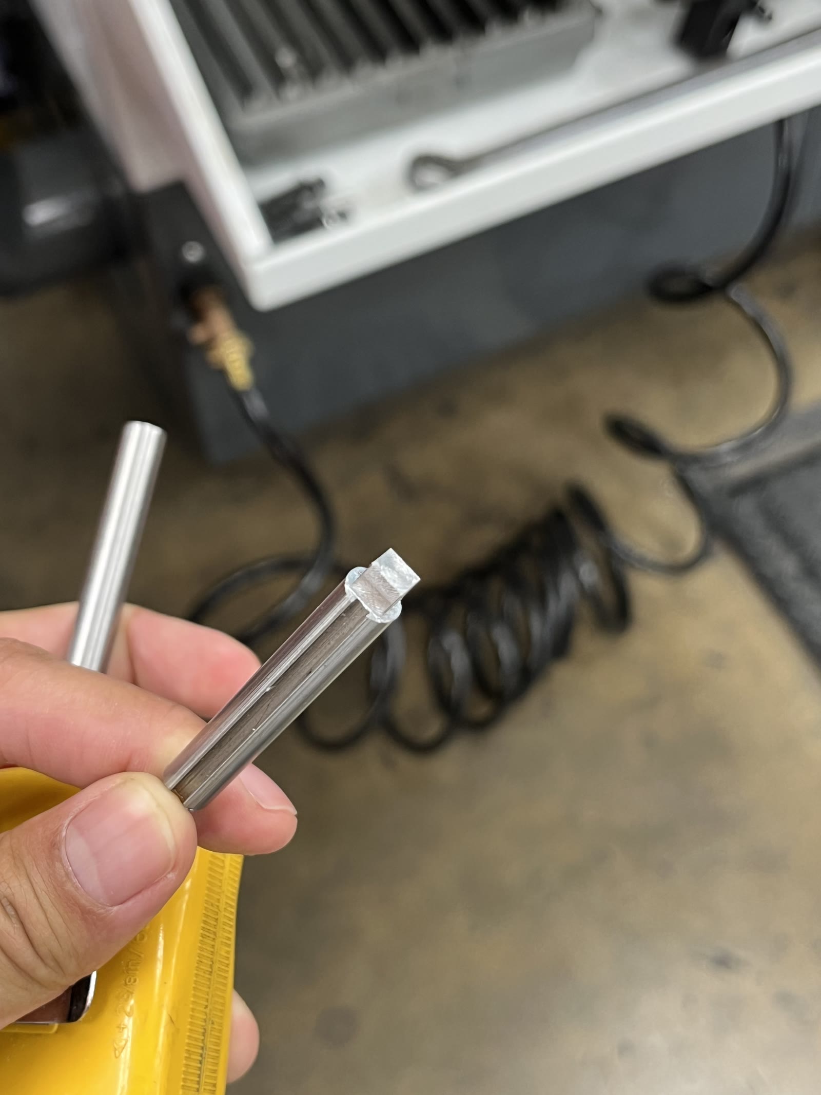
From there, the design moved into manufacturing. I optimized the parts for ease of machining. Most components were waterjet cut, with holes finished on a mill. The one part that required more specialized work was a keyed shaft, which I machined on a lathe using keyed stock.
The final assembly came together under significant time pressure before competition. The brake pedal itself was left unfinished, so as a stopgap I fabricated a vertical stick in place of a proper pedal face. Completing that pedal, machining the stick into its final form, and refining the design remain on the list for future iterations.
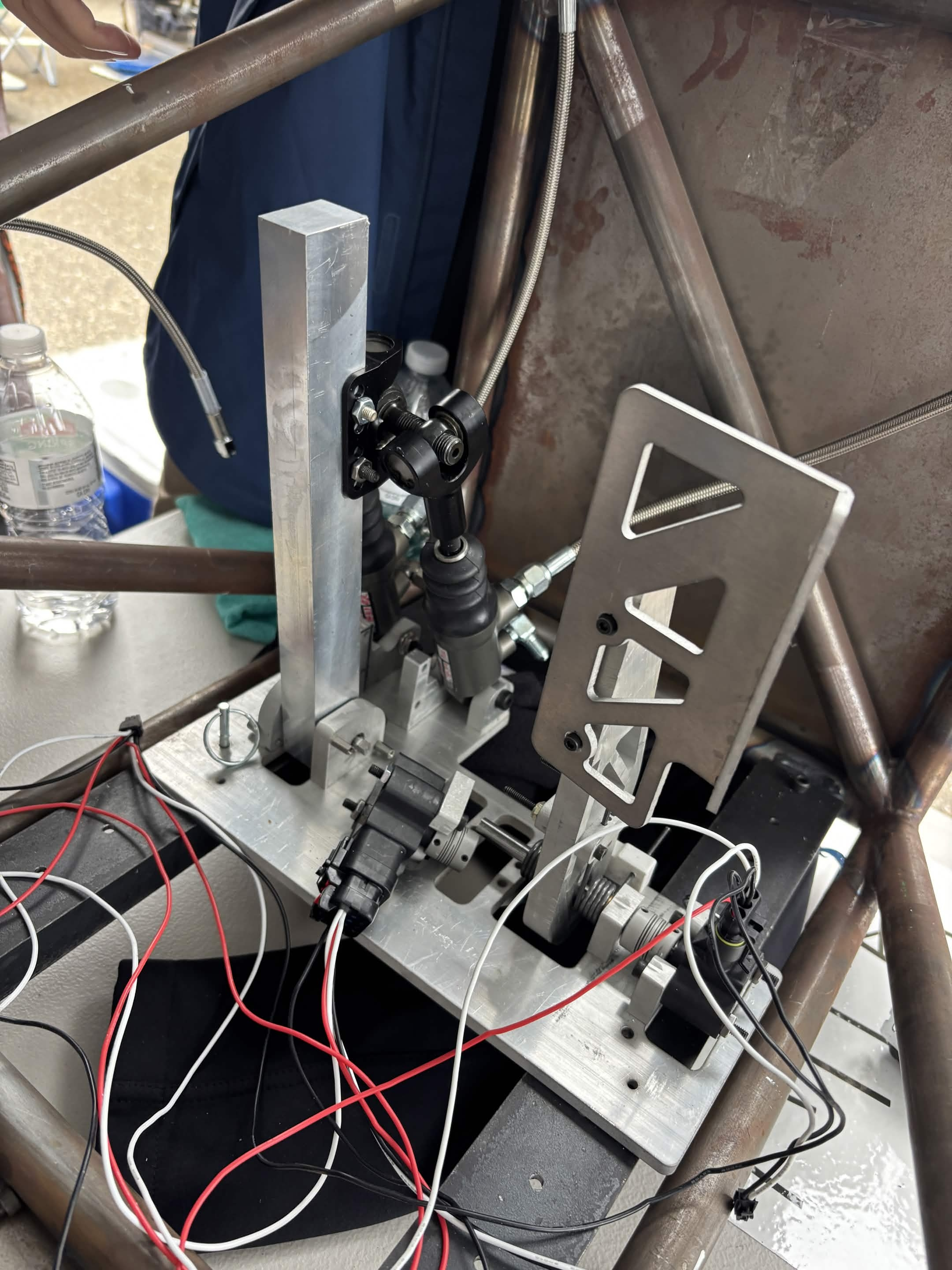
Despite the rushed finish, the pedalbox came in under ten pounds, notably lighter than comparable units on the market, and cost roughly fifty dollars in aluminum stock, with the remainder sourced from scrap. All machining was done in house.
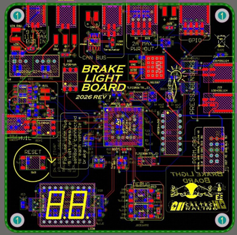
Each sensor in the assembly feeds back to the brake pedal PCB, which communicates with the car's electronics to trigger the brake light and track accelerator position. A future upgrade will replace the current Honeywell sensors with something more compact. I also wasn't able to 3D print a footrest in time, which is planned for a later build. The pedalbox includes quick release locking pins so drivers can swap in and out easily, accommodating everyone from the 5th percentile male to the 95th percentile female.
Gallery