2026
Rear Wing Endplate Aerodynamic Design
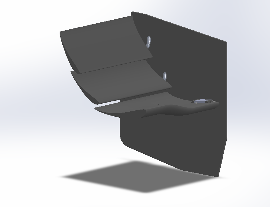
- Problem
- The rear wing endplate needed to reduce drag without sacrificing downforce, while staying manufacturable as a single flat sheet-stock part on the team's existing machining process.
- Approach
- I used a one-variable-at-a-time design process in Star-CCM+, iterating through cutout geometry, top cutout angle sweeps, rear bottom edge treatments, and louver placement on a flat endplate pattern.
- Result
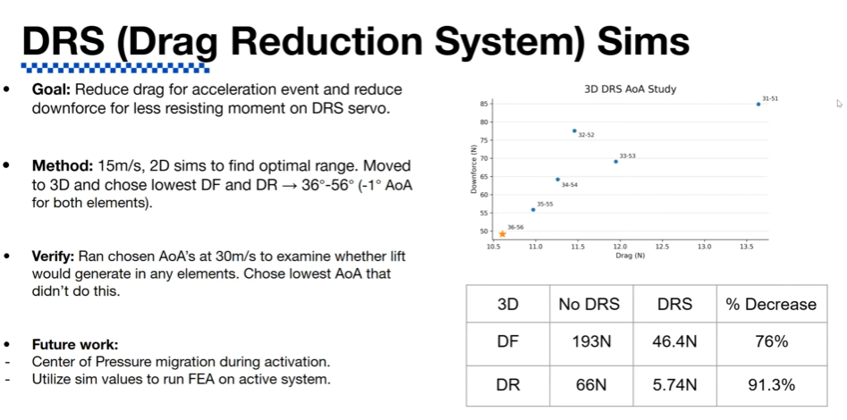
- The final endplate configuration produced 193.00 N of downforce (+4.89%) and 66.00 N of drag (−4.35%), representing a 9.00 N increase in downforce while reducing drag by 3.00 N. With DRS, this improves to a 91.3 percent drag reduction from 66 N to 5.74 N.
Rear Wing Endplate Aerodynamic Design
I designed and simulated a rear wing endplate aimed at cutting drag without giving up downforce, and ideally adding a small amount of downforce over the baseline geometry. The endplate also had to stay a single flat plane so it could be produced from sheet stock on the team's existing machining process, which ruled out any three-dimensional forming and kept every design decision tied to a flat, cuttable pattern.

I started from a simple constraint: a bigger endplate reduces tip vortices and helps the car's aero package at the lower speeds it operates at, so material only came off the plate where I could justify it aerodynamically. Early inspiration came from Formula 1 cars of the early DRS era, particularly the RB10 and RB16, whose boxy endplates and cutout placement gave me a real-world starting point. My first design pushed surface area and cutout complexity as far as I could in one step, and it performed badly in simulation: poor downforce and unstable behavior under yaw. That failure pushed me toward a one-variable-at-a-time process for the rest of the project, running each change through Star-CCM+ before layering on the next.
From there I worked through a series of isolated studies: a cutout behind the third wing element that turned out to trip flow separation earlier than intended rather than help it, a top cutout swept across height, width, and angle that found an 85-degree angle to be the most efficient at reducing frontal area and drag, and a rear bottom cutout where switching from a simple fillet to a 10-degree angled cut finally addressed the trailing tip vortices along that edge.
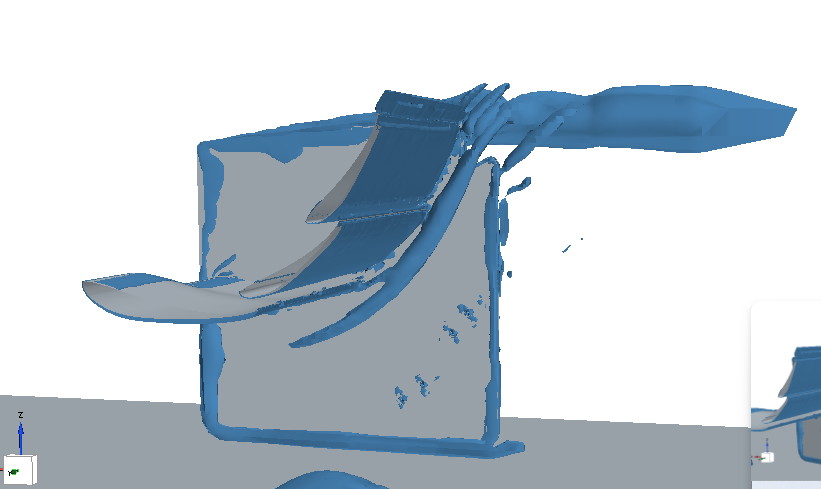
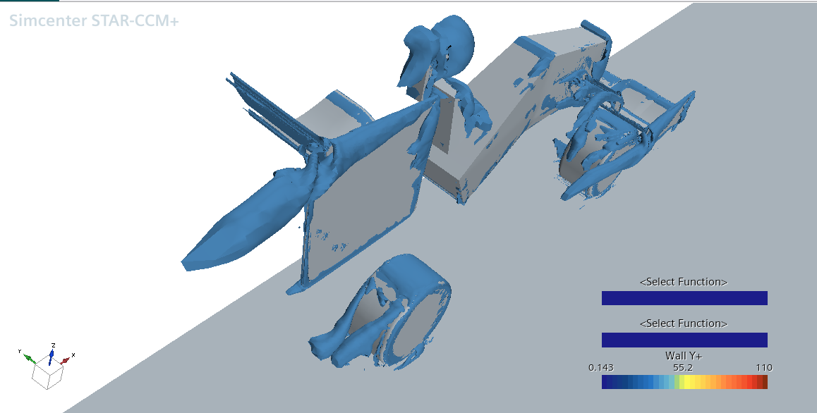
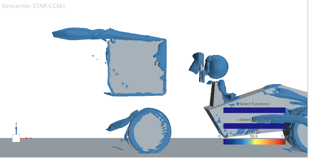
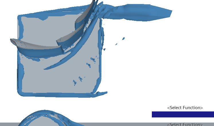
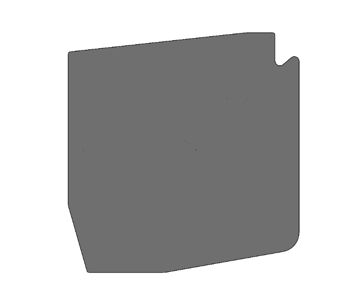
The final geometry combined all of these features into one flat pattern with the fillets radiused to reduce local stress and flow separation. In simulation, the final endplate configuration produced 193.00 N of downforce (+4.89%) and 66.00 N of drag (−4.35%), representing a 9.00 N increase in downforce and a 3.00 N reduction in drag relative to the initial configuration. This improved the downforce-to-drag ratio from 2.67 to 2.92 (+9.36%), indicating a measurable improvement in overall aerodynamic efficiency. The rear wing itself actually shed a little downforce and drag in isolation, consistent with removing surface area from it directly, but its own efficiency still improved from 2.755 to 2.805, and the net effect across the rest of the car more than made up the difference. I also tracked Wall Y+ between the baseline and final runs as a sanity check on mesh quality, and flagged that the two simulations weren't meshed identically, so I treated that as a caveat on the results rather than a clean before-and-after comparison. The plan going forward is to manufacture the plate by laser-cutting a 25 by 25 inch foam plug and laying up carbon over it, which keeps the fillets and cutout details close to the CAD, and to revisit a notch behind the third element and finer-resolution angle sweeps in a future iteration.
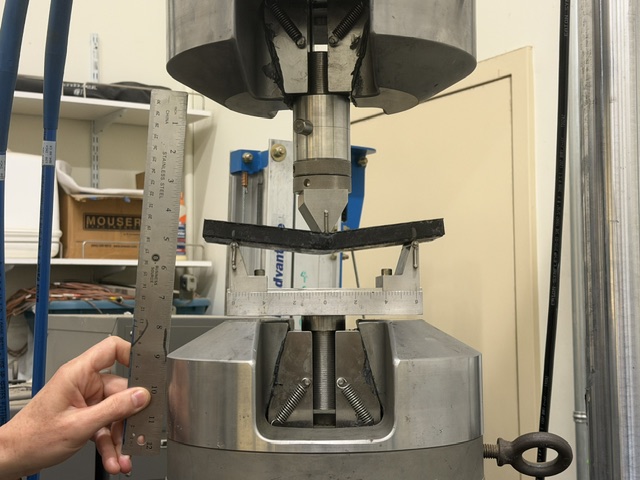
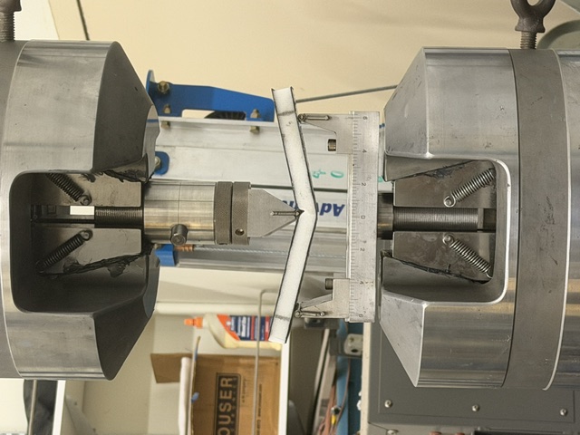
Before finalizing the layup, I tested core material selection for the endplate itself. I ran eight identical PET-CF cores against aerospace foam cores, each sandwiched in an identical carbon fiber layup, and loaded them to shear failure on a 55-kip MTS 810 servohydraulic frame in Professor Valeria La Saponara's composites lab at UC Davis. The PET-CF cores withstood an average of 40 N more force before failure than the aerospace foam, so I selected PET-CF as the core material going into the final layup.
Drag Reduction Assembly
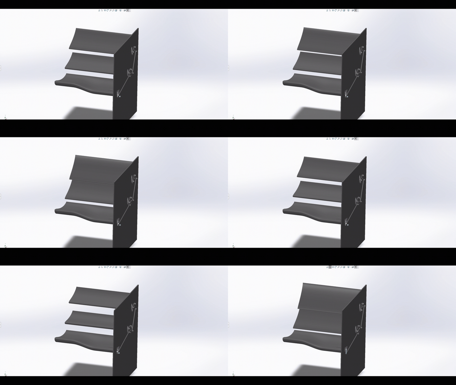
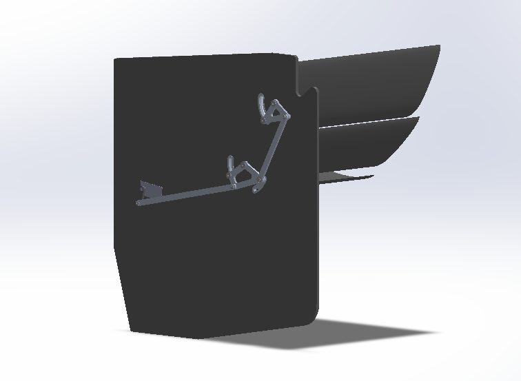
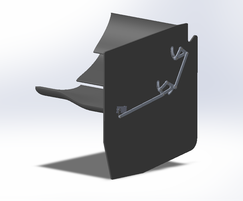
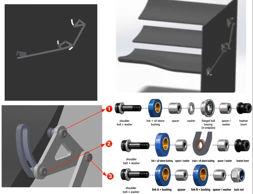
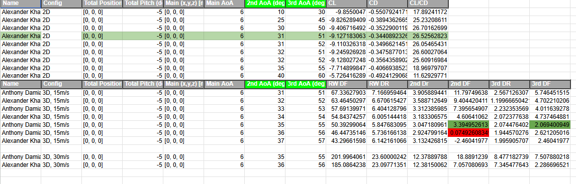
Alongside the endplate, I designed the DRS (Drag Reduction System) setup that opens the second and third wing elements to cut drag on straight-line acceleration and take load off the actuating servo. I found the target angles by sweeping the angle of attack of both elements together, starting with a broad 2D scan at 15 m/s to find the productive range, then narrowing to a tighter 3D sweep across paired angles from 31°-51° through 36°-57°. I picked 36°-56° as the lowest combined downforce and drag in that set, then verified it at 30 m/s to rule out either element stalling into lift instead of downforce at higher speed before locking it in. With DRS deployed at that setting, full-car downforce dropped from 193 N closed to 46.4 N open (a 76% reduction) and drag dropped from 66 N to 5.74 N (a 91.3% reduction), which lines up well with the same closed-wing baseline I measured for the endplate itself. From there I designed the actuation hardware: a servo-driven linkage that rotates both elements together through a bell crank, riding on three different pivot arrangements (a bearing pivot at the endplate, a track pivot, and a link-to-link pivot) built from shoulder bolts, oil-sleeve bushings, and heatset inserts so each joint rotates freely without binding.
Links
Gallery